Building an STMicroelectronics Sensor Node
Predictive Maintenance application with STMicroelectronics STWIN SensorTile Wireless Industrial Node

Image Source: 24Novembers/shutterstock.com
By Joseph Downing, Mouser Electronics
Edited April 27, 2021 (Originally Published August 24, 2020)
The human body can be looked at as a complicated machine, needing fuel to run, expending energy to perform tasks.
Like other machines, the human body can begin to have limited function or even break. To counter this, many of
us schedule routine exams and yearly checkups to ensure everything is in order or adjust our lifestyle as
necessary. Many devices are even available on the market that can help notify us of changes in our health, such
as blood-pressure cuffs, smartwatches that measure blood-oxygen levels, activity levels, sleep trends, and even
abnormal heart rate. These types of devices can help monitor changes and potentially warn someone before
something more serious occurs.
Much like our own bodies, having equipment such as a Heating, Ventilation, and Air Conditioning (HVAC) system or
a vehicle suddenly cease to function can be frustrating as well as time-consuming and costly, not to mention the
inconvenience. In Industrial Internet of Things (IIoT) applications, the use of various sensors can allow you to
monitor equipment to help determine its condition, a term called Predictive Maintenance. This monitoring
approach provides the potential for cost savings by minimizing downtime and scheduling necessary maintenance to
prevent unexpected failures or accidents.
Here, we will demonstrate how to use the STMicroelecronics’ SensorTile Wireless Industrial Node (STWIN) to
develop an IIoT wireless sensor node that can be monitored remotely. We will provide a list of necessary
hardware and software resources and instructions on installing and configuring both. Once completed, this will
provide you with a configurable dashboard that will allow you to view data from any number of sensors, such as
vibrometer, temperature, and motion, to name a few.
Project Materials and Resources
The materials needed for this project are pretty straightforward because the STWIN SensorTile development Kit
includes the STLINK-V3MINI hardware debugger. STMicroelectronics does provide a demo that can be run out of the
box. For this project, we will be utilizing the STEVAL-STWINWFV1 wireless expansion module to run one of the
other available demos. You can find a quick link to a shared project bill of materials (BOM) here. Along with the
hardware, you will need certain software such as the STM32CubeProgrammer and the Function Pack FP-IND-PREDMNT1.
If you already have some of these installed, you can skip over most of the system configuration section. If not,
links and the necessary steps for installing the required software are provided in the following.
Project Code and Software Links
Project Technology Overview
Figure 1: STMicroelectronics STWIN SensorTile Wireless Industrial Node
(Source: Mouser Electronics)
STMicroelectronics STWIN SensorTile Wireless Industrial Node (STEVAL-STWINKT1) (Figure 1) is a
comprehensive development kit and reference design that simplifies prototyping and testing of advanced IIoT
applications, such as condition monitoring and predictive maintenance. The STEVAL-STWINKT1 is based on a Core
System Board, which features a wide range of embedded industrial-grade sensors. The Core System Board features
an ultra-low-power Arm® Cortex®-M4 Microcontroller and a range of industrial-grade
sensors for 9-DoF motion sensing, vibration analysis across a wide range of vibration frequencies, including
very high-frequency audio and ultrasound spectra, and high-precision local temperature and environmental
monitoring.
The STEVAL-STWINKT1 Development Kit is complemented with a rich set of software packages and optimized firmware
libraries, and a cloud dashboard application, all provided to help speed design cycles for end-to-end solutions.
Features
- Multi-sensing wireless platform Implementing vibration monitoring and ultrasound detection
- Built around STWIN core system board with processing, sensing, connectivity, and expansion capabilities
- STM32L4R9ZIJ6 Ultra-low-power Arm®
Cortex®-M4 MCU with FPU
- Micro SD card slot for standalone data logging applications
- Connectivity
- Wireless BLE4.2 (onboard module)
- Optional Wi-Fi (with STEVAL-STWINWFV1 expansion board)
- Wired RS485
- USB OTG connectivity
- Wide range of Industrial IoT sensors
- ISM330DHCX 3D
accelerometer + 3D Gyro iNEMO inertial measurement unit with machine learning core
- IIS2DH Ultra-low-power
high-performance MEMS motion sensor
- IIS2MDC Ultra-low-power
3-axis magnetometer
- LPS22HH Digital
absolute pressure sensor
- HTS221 Relative
humidity and temperature sensor
- STTS751 Low-voltage
high-accuracy digital local temperature sensor
- IMP34DT05 Industrial-grade
digital MEMS microphone
- MP23ABS1 Wideband
analog MEMS microphone
- IIS3DWB Ultra-wide
bandwidth MEMS
vibrometer
- Modular architecture, expandable via onboard connectors
- STMOD+ and 40-pin flex general purpose expansions
- 12-pin male plug for connectivity expansions
- 12-pin Female Plug for Sensing Expansions
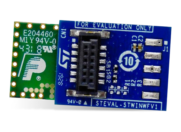
Figure 2: STMicroelectronics STEVAL-STWINWFV1 Wi-Fi® (Source:
Mouser Electronics)
STMicroelectronics STEVAL-STWINWFV1 Wi-Fi® (Figure 2) adds 2.4GHz Wi-Fi
connectivity to the STWIN SensorTile Wireless Industrial Node Development Kit (STEVAL-STWINKT1). The
STEVAL-STWINWFV1 board is connected via a dedicated 12-pin connector to the core system board. The Inventek
Systems ISM43362-M3G-L44-E Module, which has an integrated TCP/IP stack, is IEEE® 802.11 b/g/n
compatible, has full Federal Communications Commission (FCC), IC, Japan, and CE module certification.
Features
- Wi-Fi Adapter for STWIN SensorTile Wireless Industrial Node Development Kit (STEVAL-STWINKT1)
- Plugs into STWIN Core System Board via dedicated 12-pin connector
- Single 3.3V power supply input
- ISM43362-M3G-L44-E Wi-Fi Module:
- 802.11 b/g/n compatible based on Broadcom MAC/baseband/radio device
- Supports Cypress WICED SDK
- Fully contained TCP/IP stack
- STM32F205 host processor
- Host interface: SPI up to 25MHz
- Network features ICMP (Ping), ARP, DHCP, TCP, UDP
- Low power operation with low power modes
- Secure Wi-Fi Authentication WEP-128, WPA-PSK (TKIP), WPA2-PSK
- CE-, FCC-, and IC-certified
- RoHS-, China RoHS-, and WEEE-compliant
Figure 3: STMicroelectronics STLINK-V3SET Modular In-Circuit Debugger
(Source: Mouser Electronics)
STMicroelectronics STLINK-V3SET Modular In-Circuit Debugger (Figure 3) is used for
debugging and programming the STM8 and STM32 microcontrollers. The debugger is composed of a main module and a
complementary adapter board. The SWIM and JTAG/SWD interfaces communicate with any STM8 or STM32 microcontroller
located on an application board.
The STLINK-V3SET provides a Virtual COM port interface allowing the host PC to communicate with the target
microcontroller through one Universal Asynchronous Receiver/Transmitter (UART) and bridge interfaces (SPI,
I2C, CAN, General Purpose Inputs/Outputs). This allows for programming of the target through a
bootloader. The modular architecture of STLINK-V3SET enables to extend its main features through additional
modules like the adapter board.
Features
- Stand-alone probe with modular extensions
- Self-powered through a USB connector (Micro-B)
- USB 2.0 high-speed compatible interface
- Direct firmware update support (DFU)
- JTAG / serial wire debugging (SWD) specific features:
- SWIM specific features (only available with adapter board MB1440):
- Virtual COM port (VCP) specific features:
- Multi-path bridge USB to SPI/UART/I2C/CAN/GPIOs specific features:
- Drag-and-drop Flash programming
- Two color LEDs: communication, power
Configuring your System
Java Software (Optional)
This step is optional if your Java software is installed and updated on your computer; however, if you are
receiving Java Environment errors, we suggest downloading either AdoptOpenJDK or Zulu JDK
FX version 8. For the instruction in this project, we have opted to use Zulu 8.48.0.51 JDK FX
8.0.262b19. Once this version of Zulu is downloaded, simply navigate to the download location and extract the
files. It is important to remember where you extracted the files, which will be relevant later in the project.
STM32CubeProgrammer
- Navigate to link for STM32CubeProgrammer v2.5.0 (or
higher).
- Click the Get Software (Figure 4)
Figure 4: STM32CubeProgrammer Software Download Link (Source:
STMicroelectronics)
- Accept agreement.
- Log in to an existing account or create a new one. The download should begin automatically.
- Once downloaded, locate the file, and extract the contents (Figure 5).
Figure 5: Extracting STM32CubeProgrammer (Source: Mouser Electronics)
Using Zulu as the selected Java software will make the installation of the STM32CubeProgrammer different than a
typical software installation and will require using the cmd program. If you are using Oracle or AdoptOpenJDK,
you can simply execute the installation program and follow all onscreen instructions.
- Press Win-S on your keyboard and type in
- Right click the icon and select Run as Administrator.
- Change directories to the location of the STM32CubeProgrammer setup program.
cd C:\Users\**********\Downloads\en.stm32cubeprog_v2-5-0
- Next, execute the Zulu Java program by copying and pasting the following command path.
C:\Users\**********\Downloads\zulu8.48.0.51-ca-fx-jdk8.0.262-win_x64\zulu8.48.0.51-ca-fx-jdk8.0.262-win_x64\bin\java.exe
        -jar SetupSTM32CubeProgrammer-2.5.0.exe
Once installed, you can edit the icon on your desktop to target the java application by right clicking the
STM32CubeProgrammer iconàselecting propertiesàand substituting the target for the path listed
below (Figure 6). (Note: You will need to adjust your path for the location of the Zulu JDK FX
on your system)
"C:\Users\**********\Downloads\zulu8.48.0.51-ca-fx-jdk8.0.262-win_x64\zulu8.48.0.51-ca-fx-jdk8.0.262-win_x64\bin\java.exe"
        -jar STM32CubeProgrammer.exe
Figure 6: STM32CubeProgrammer Windows Properties (Source: Mouser
Electronics)
FP-IND-PREDMNT1
- Navigate to the link for FP-IND-PREDMNT1.
- Click the Get Software link like shown in (Figure 4) when downloading the
STM32CubeProgrammer.
- Accept agreement.
- Log in to an existing account or create a new one.
- Once downloaded, locate the file, and extract the contents just as before.
Programming your Device
Hardware Setup
Before we program the device, we will need to begin by first connecting the STEVAL-STWINWFV1
Wi-Fi® module and STLink-V3MINI Debugger to your STWIN, as well as to your PC.
- Plug the STEVAL-STWINWFV1 Wi-Fi® module into the STWIN at location CN3.
- Connect the included JTAG cable from location J2 on the STWIN to location CN5 on the STLink-V3MINI Debugger.
- Next, connect one Micro USB cable from your PC to location J13 on the STWIN
- Lastly, connect one Micro USB cable from your PC to the MicroUSB header on the STLink-V3MINI Debugger.
Software Setup
Once you connect the device to your PC, we will need to complete several steps to program the device.
- Begin by Opening the STM32CubeProgrammer.
- Verify your settings along the right side of the window match what is displayed (Figure 7).
- Click the Connect button on the upper right side of the window (Figure 7).
Figure 7: STM32CubeProgrammer Window (Source: Mouser Electronics)
- Select the erase button in the lower-left side of the window (Figure 8).
- Click OK when the pop up asks if you are sure you want to erase the full chip flash memory.
- Click OK once again when the process is completed.
Figure 8: STM32CubeProgrammer Erase (Source: Mouser Electronics)
- Now that you have erased the device, we can program the device by clicking Open file at the
top left of the window.
- Navigate to the folder where you extracted the file FP-IND-PREDMNT1 and locate the Predictive Maintenance
Demo Binary file.
C:\Users\**********\Downloads\en.fp-ind-predmnt1\STM32CubeFunctionPack_PREDMNT1_V2.2.0\Projects\STM32L4R9ZI-STWIN\Demonstrations\Predictive_Maintenance_WIFI\AWS\Binary
- Highlight the file and click Open.
- Once loaded, click the Download button at the top right of the window (Figure 9).
Figure 9: STM32CubeProgrammer Download Button (Source: Mouser
Electronics)
- Click OK on the completion prompt and select Disconnect in the top right corner to
Disconnect the board from the programmer.
Running the Application
You have completed programming the STWIN and now need to interface to the device. For this, you will need a
terminal program. In this project, we will be using Tera Term and will demonstrate the necessary configurations.
Terminal Interface Configuration
- Disconnect the STLink-V3MINI Debugger and press the reset button on the STWIN.
- Open Tera Term and use the Serial option, selecting the correct Port from the list in the drop-down box and
select OK (Figure 10).
Figure 10: Tera Term New Connection Window (Source: Mouser Electronics)
- Click the Setup menu button along the top of the window and select
Terminal
- Change the New-line settings
- Receive: AUTO
- Transmit: CR+LF
- Ensure the Local echo is checked and click OK (Figure
11).
- Press the reset button on the STWIN.
Figure 11: TeraTerm Terminal Setup Window (Source: Mouser Electronics)
Configuring the Device to Broadcast
Now that you have configured the terminal interface, you should have something similar to the following screen
displayed (Figure 12). Here you will need to input your network SSID, select the correct
security mode, and if necessary, input the network password. (NOTE: Hidden SSID’s can be a problem, and it
is strongly recommended that you do not use.)
Figure 12: STWIN Wireless Configuration Screen (Source: Mouser
Electronics)
Next, we will need to navigate to https://dsh-predmnt.st.com/ using the
login credentials for your my.st account and accepting the terms of usage to connect. This will allow us to add
a new device to our dashboard, and finish configuring our device to connect.
- Click the three parallel bars in the top left-hand corner of the screen (Figure 13).
- Select Configuration from the left side menu.
- Select + to add a new device from the upper right-hand side of the window.
Figure 13: ST Dashboard Configuration (Source: Mouser Electronics)
- Next, input a device name (anything you choose) into the Device ID field and click
Add at the bottom right of the window (Figure 14).
This will generate the device credentials in the next window that you will securely connect your device.
Figure 14: Device Creation Window (Source: Mouser Electronics)
You must download and remember where you saved this file, as once you confirm and close the window, you will no
longer have access to these credentials. Once downloaded, copy the IoT Endpoint highlighted in blue at the
bottom of the window before closing the window (Figure 15).
Figure 15: Credentials Window (Source: Mouser Electronics)
- Pull up your terminal window again and paste the IoT Endpoint.
- Provide the Device ID you created from within the Dashboard.
- Locate the downloaded credentials and extract the file. This should provide you with three files.
- Locate the file named root.ca.pem and right click on the file, selecting Edit or
Open With Notepad.
- Copy the contents of this file by simply hitting CTRL-A followed by
CTRL-C.
- Bring up your terminal window and right click to paste your credentials, pressing OK to complete
(Figure 16).
Figure 16: Pasting the Root Credentials (Source: Mouser Electronics)
You’ll now be asked for the device certificate. This will require you to complete the same set of steps
just outlined using the DeviceID.cert.pem file. This file will match the name you chose for your device. After
this, you will be asked to complete the steps for a third time, now with the Device Private Key file labeled
DeviceID.private.key substituting your specific device name. Once the last key is entered, you should soon begin
to see topics published (Figure 17).
Figure 17: STWIN publishing through the MQTT Broker (Source: Mouser
Electronics)
Adding your Device to the Dashboard
Now, of course, is the best part. Once you’ve connected and the device is publishing sensor data, simply
return to the ST Dashboard and select the Dashboard from the top of the window. Clicking the Add Device should
provide you with a list of available options, and selecting your newly created device will provide you a full
feature set of useful data (Figure 18). From here, you can set thresholds and utilize the Asset
Condition Monitoring feature or even create warnings for specific events.
Figure 18: Published Sensor Display (Source: Mouser Electronics)
Explore the other functionalities of the dashboard, such as Condition Monitoring, which allows you to trigger
warnings and alarms based on data value, and Data Lake, to export sensor data for offline analysis.
Closing
It’s easy to see both why and how your equipment can benefit from predictive maintenance.
STMicroelectronics provides you the tools necessary to easily design and implement own solutions along with an
easy-to-configure dashboard to allow you to visualize your data from virtually anywhere. Coupled with the
possibility of Machine Learning both on the device and in the cloud, predictive maintenance has the potential to
increase safety, reduce cost, and minimize equipment downtime. Of course, we would love to know if you’ve
completed this project yourself or even made improvements or modifications. Reach out and let us know at Facebook, Twitter, or LinkedIn.
Author Bio
Joseph Downing has worked for Mouser Electronics
for six years, coming on in 2011 as a Technical Support Specialist and later moving to Technical Content
Specialist.
Joseph has worked in the electronics industry for 20+ years with companies such as Intel, Radisys, and Planar.
An avid Maker, Joseph helps to manage and provide technical projects and material to the Application and Technology
site on Mouser.com as well as Trade Shows. Joseph can be
reached at joseph.downing@mouser.com.


